Utah Broadband | Fiber Mapping System
Redesigning how a high speed internet provider plans their fiber layout
Project Overview
Role: Lead UX/UI Designer
Tasks: UX Design, UI Design
Team: 2 Engineers, 1 Designer
Duration: 2 months
TL;DR
Redesign a fiber mapping system to allow less onboarding and headaches as the original software was designed solely for function without incorporating any user needs.
Project Summary
As a high speed internet provider, Utah Broadband has a fiber network service. A large part of their business included field work of digging, laying out, and connecting fiber to a client’s house. To ensure that this could be done with minimal errors, Field Technicians would use a software created inhouse to map out their fiber network. The original software was created with only function in mind and a complete mess to navigate. A full redesign would be needed to allow the Field Technicians to use the software easily with less headaches.
Project Functions
The Fiber Mapping System (FMS) allows the company to keep track of all the fiber lines they have laid out previously, and also lets them plan upcoming installations.
FMS would keep track of all lines, access points, terminals, sites, and much more as well as the location of all client properties. This lets FMS function as a mapping tool as well, letting Field Technicians draw out potential fiber network lines to plan out where they would need to dig to layout the new line.
Original Application
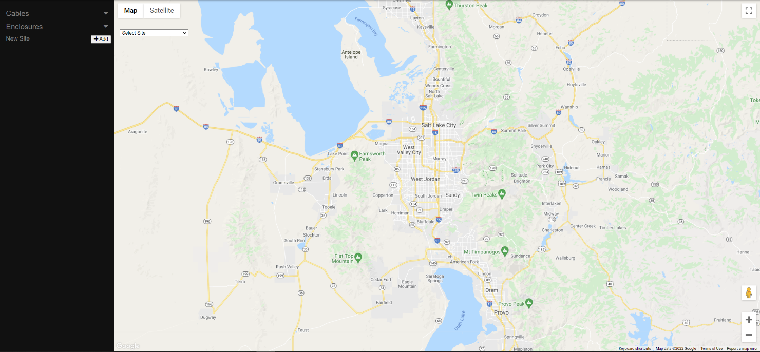
Default: Default screen when OG is loaded. New Site (+Add) button and Select Site dropdown are visible.

Dropdown: Dropdown selected

Site Default: Default view once site is selected. Note that New Site button has been replaced with New Cables (+ Submit) on the sidebar.
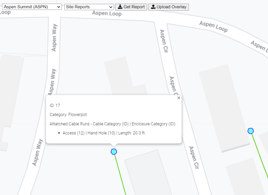
Enclosure Info: Text box on enclosure hover

Reports: Site reports dropdown. User selects report then clicks Get Report button. User's OS will ask where to download the file.
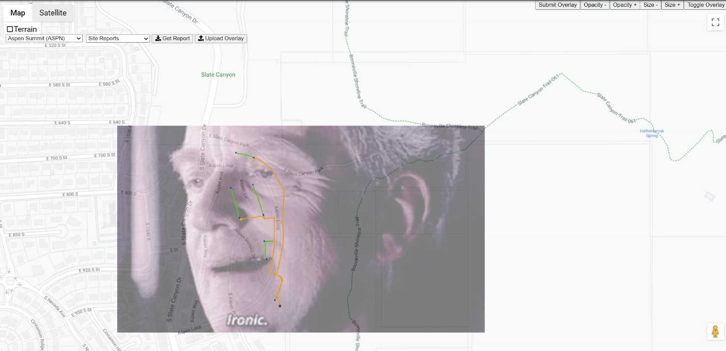
Overlays: User clicks Upload Overlay then adds file. Warning will be displayed if file is not .jpg or .png. Overlay buttons are added to the top right corner. Submit Overlay button only displays if the user has not yet submitted an overlay to a site.
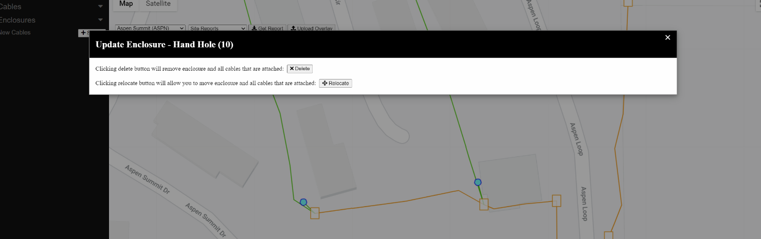
Update Enclosure: Update enclosure modal. Displays on an existing enclosure after user right clicks it. Delete will close the modal, them remove the enclosure and any associated cables on the backend.
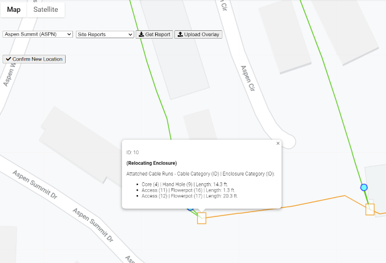
Relocate: However, if user clicks Relocate, the modal will close and a prompt will show on the hover textbox to show that is the enclosure the user is moving. User can move enclosure by clicking and dragging, then clicking the Confirm New Location button on the top left to submit to the backend.
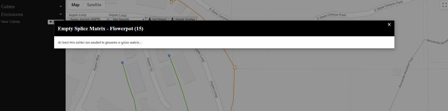
Empty Matrix: If user left clicks on an existing enclosure, and there are not at least two cables at the enclosure, a modal displays to inform the user that more than one cable is needed to splice.
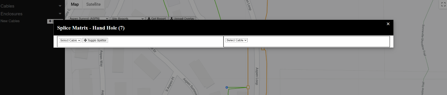
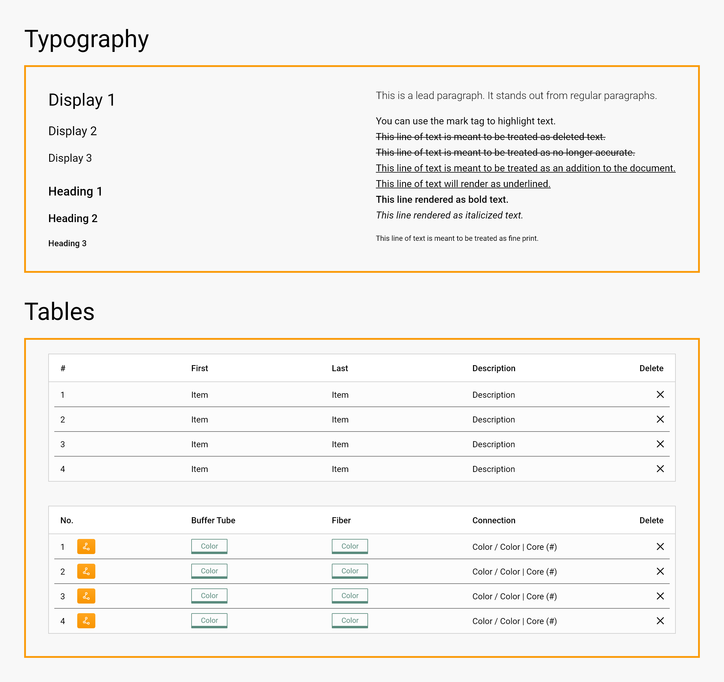
Matrix Default: Default modal view for Splice Matrix. Split between two tables with a Select Cable dropdown on either side.
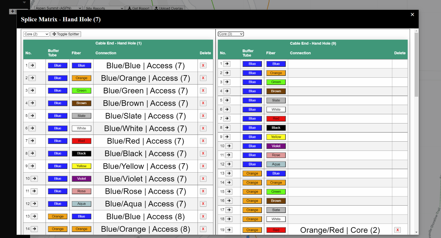
Matrix Splice: Once cables are selected on both dropdowns. Splice Matrix displays, showing how each fiber is spliced (denoted in the Connection column). Each table shows where the opposite end of the cable is located in the header.
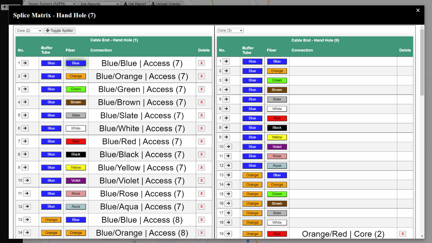
Matrix Splice Highlight: To splice two fibers, user clicks on Fiber button on one table (selection shown by the green highlight around the button, blue/blue fiber in the example image), then clicks a button on the other table. The connection column on both tables will be updated to show the new connection. To delete a cable, user clicks on the X button in the Delete column. This will update the connection column to remove the splice.
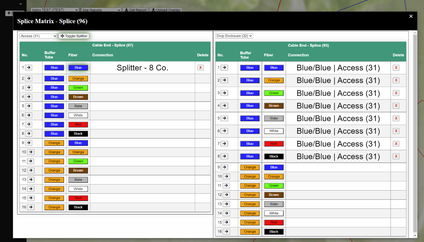
Matrix Splitter: Sometimes we use what's called a Splitter, which is a device we can connect to a single fiber that will split the connection into multiple other fibers. To use this, the user first clicks the Toggle Splitter button (shown by the green highlight) and clicks the fiber the splitter is connected to (Blue/Blue in the example image). User then clicks the fibers on the corresponding table to connect fibers to the Splitter. User can click as many times as they want until they click the Toggle Splitter button again. (Also on a minor note, I'd like to add to the connection table that a fiber is connected to a splitter. It doesn't at the moment). Like adding Blue/Blue (Splitter) | Access (31) in the case above.

Fiber Path: If a user clicks on arrow button in the Splice Matrix, the modal will close and the OG will highlight that fiber's bath back to the terminal (shown by the blue highlight). To get rid of the path highlight, a user clicks on Hide path button in the top right.

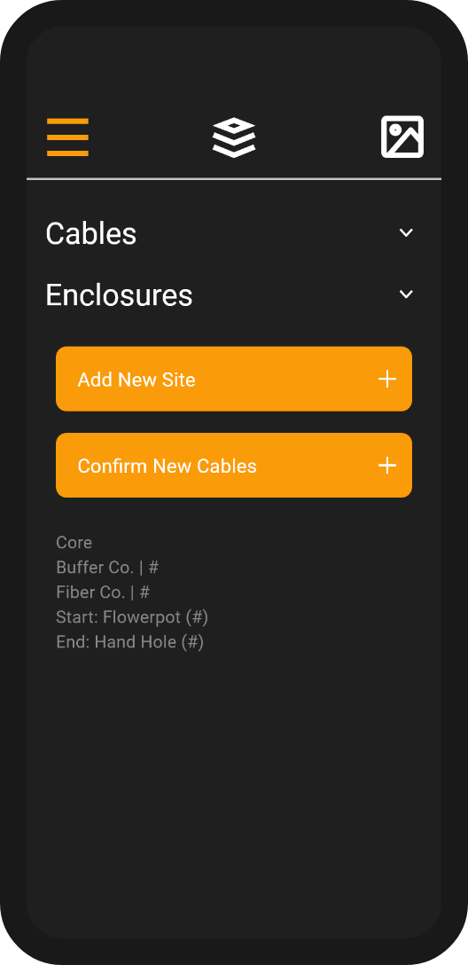
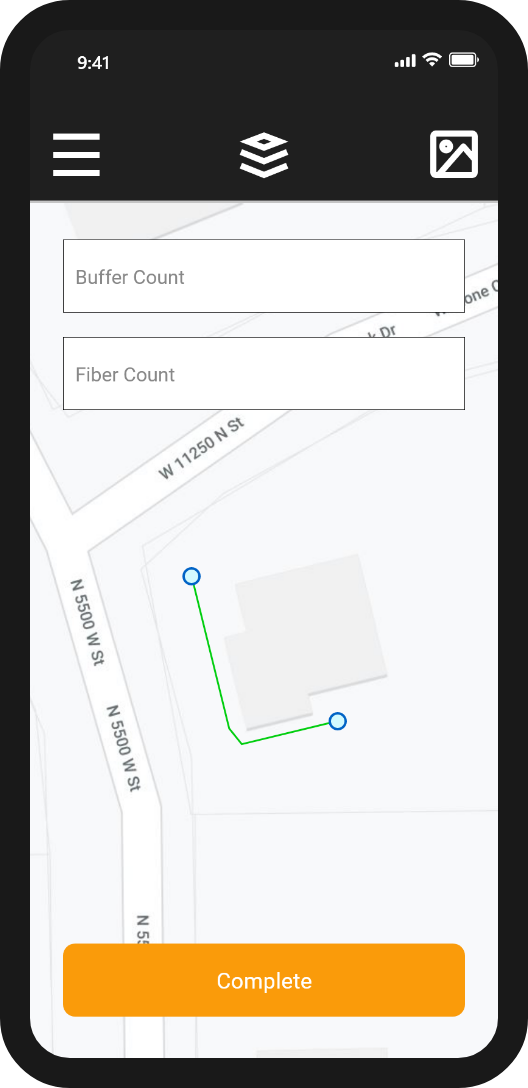
New Cable: If user selects a cable on the side menu, user can draw a new cable on the map. Once user enters the Buffer Count and Fiber Count text fields, they can click the Complete Run button to add the cable. This is represented on the side-menu, which shows what type of cable it is, the buffer/fiber counts, and where the cable starts/ends. Once user hits + Submit on the side-menu, the cable is submitted to the backend and the info on the side-menu is removed. If user hits the X button next to the new cable, the cable is removed from the map and the info on the side-menu is removed.

New Cable Enclosure: New Cables are also displayed on the enclosure hover text box.
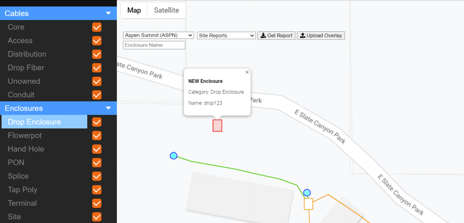
New Enclosure: If user clicks on an enclosure on the side-menu, they can add the enclosure to the map (the Enclosure Name textbox is optional). The hover window will display that this enclosure is a new one. User submits the enclosure the same way as cables. We currently do not have new enclosure added to the sidebar as it can be difficult to tell enclosures apart from giving them a name. We're trying to think of a better way to get around this.

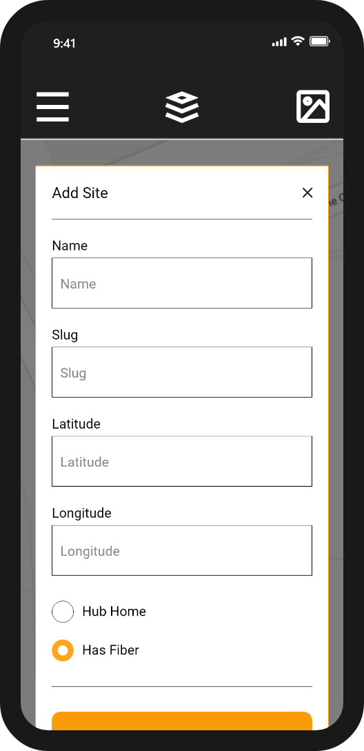
Add Site: Add Site form
Mobile Mocks


Desktop Mocks


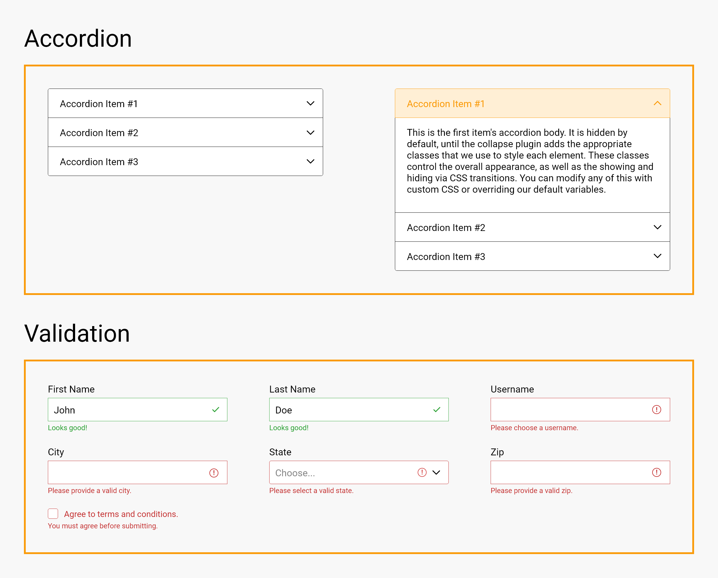
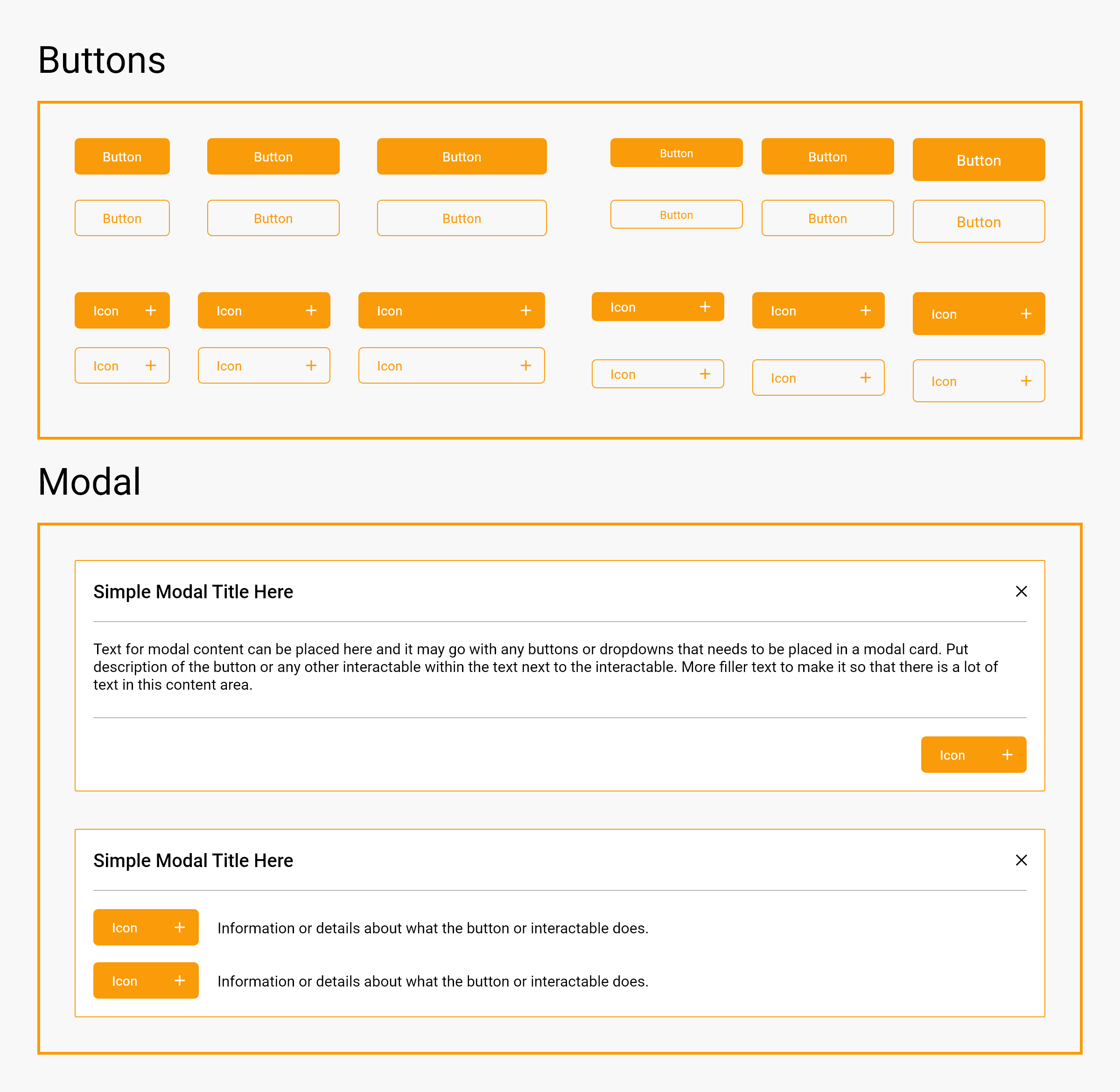
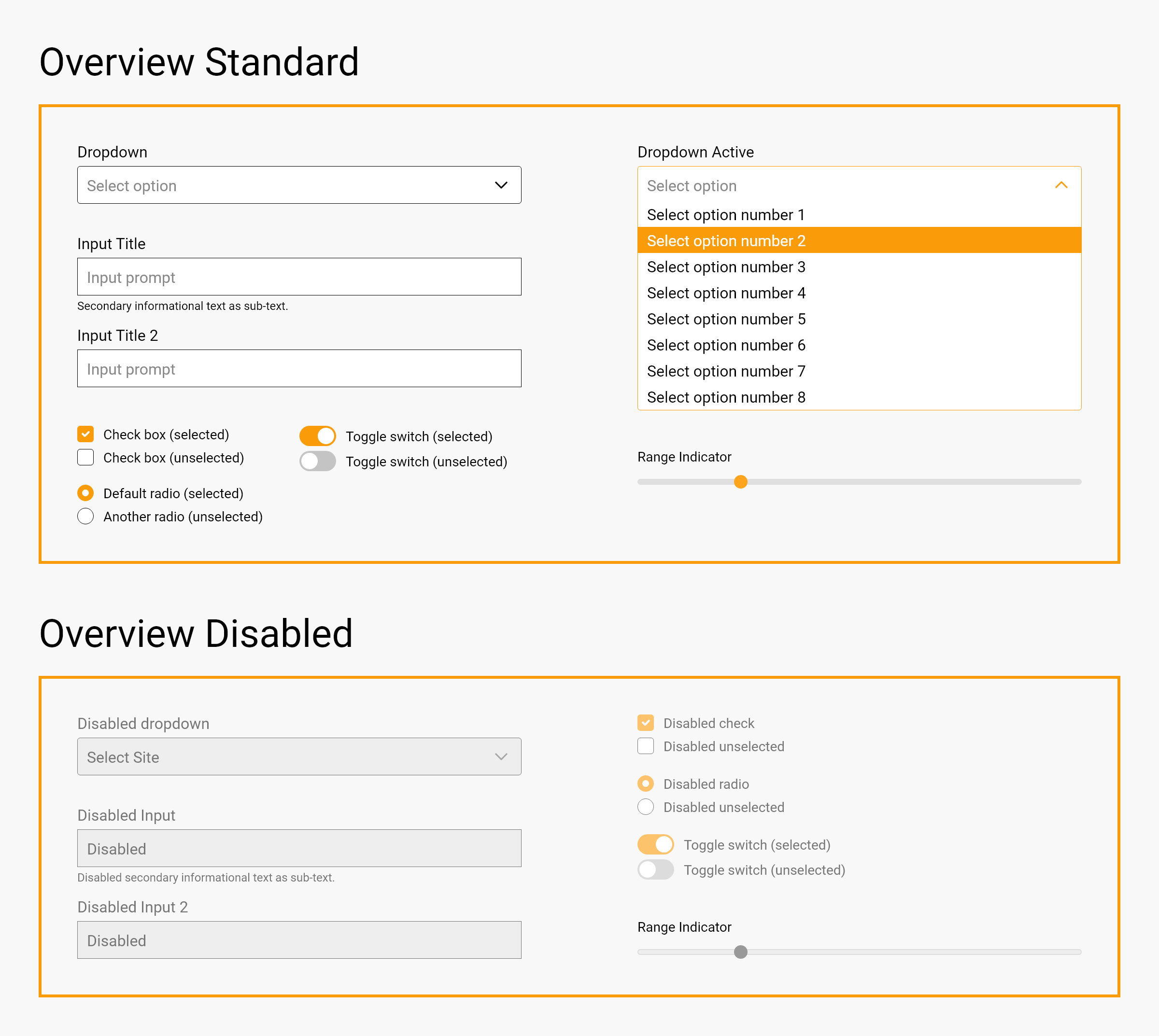
User Interface